Rocket Tracker Part 10: Tracker v0.3 Assembly & Firmware
In my last post I discussed how I was making the finishing touches on the third revision of the tracker PCB. I ordered the boards, and they arrived recently - perfectly in time to start testing the hardware on the board and get a start on writing new firmware for this new device.
Board Assembly & Testing
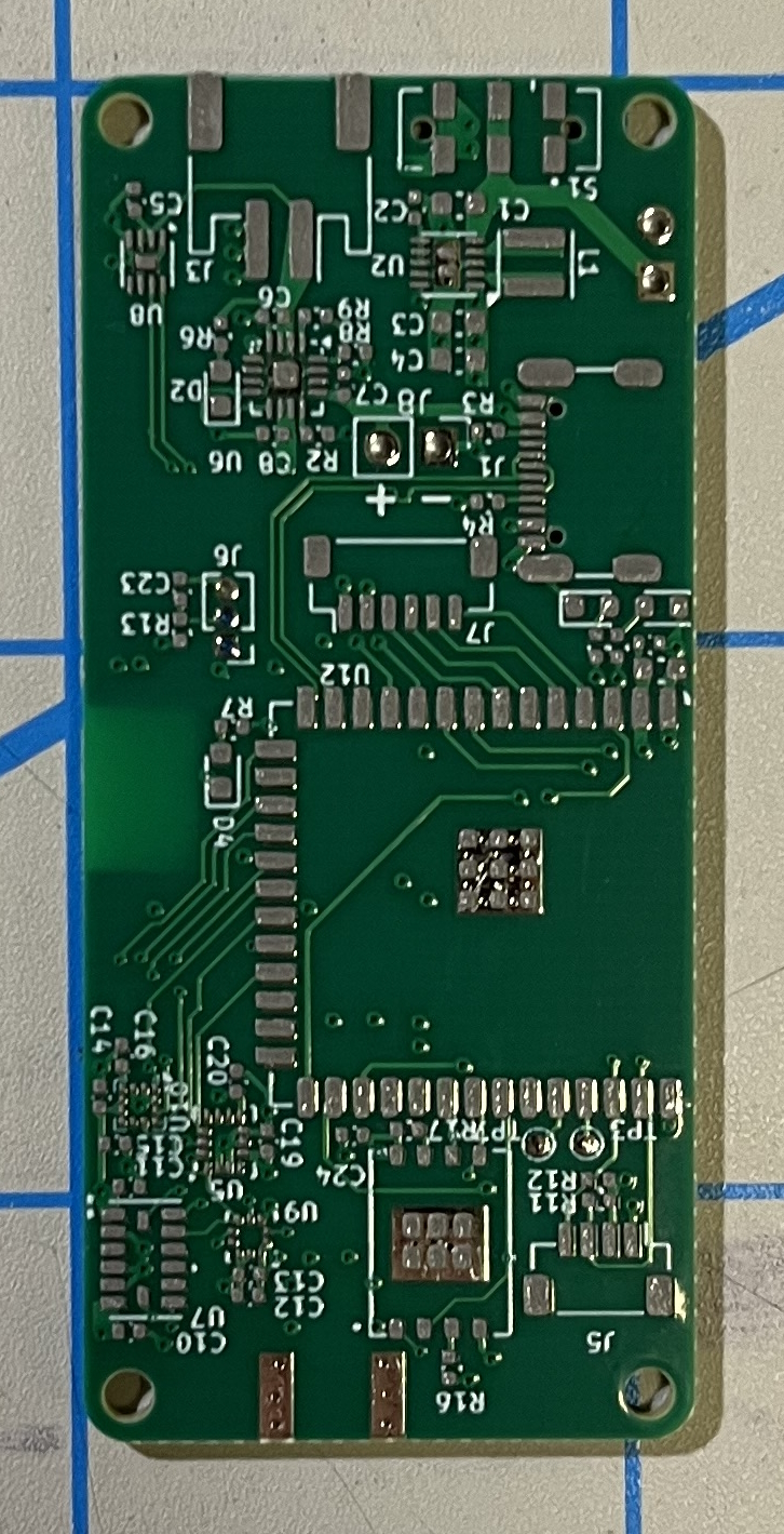
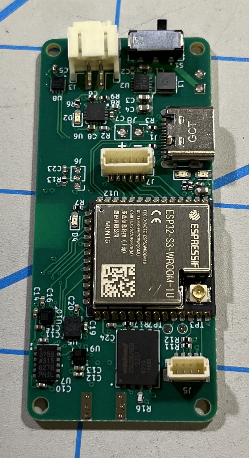
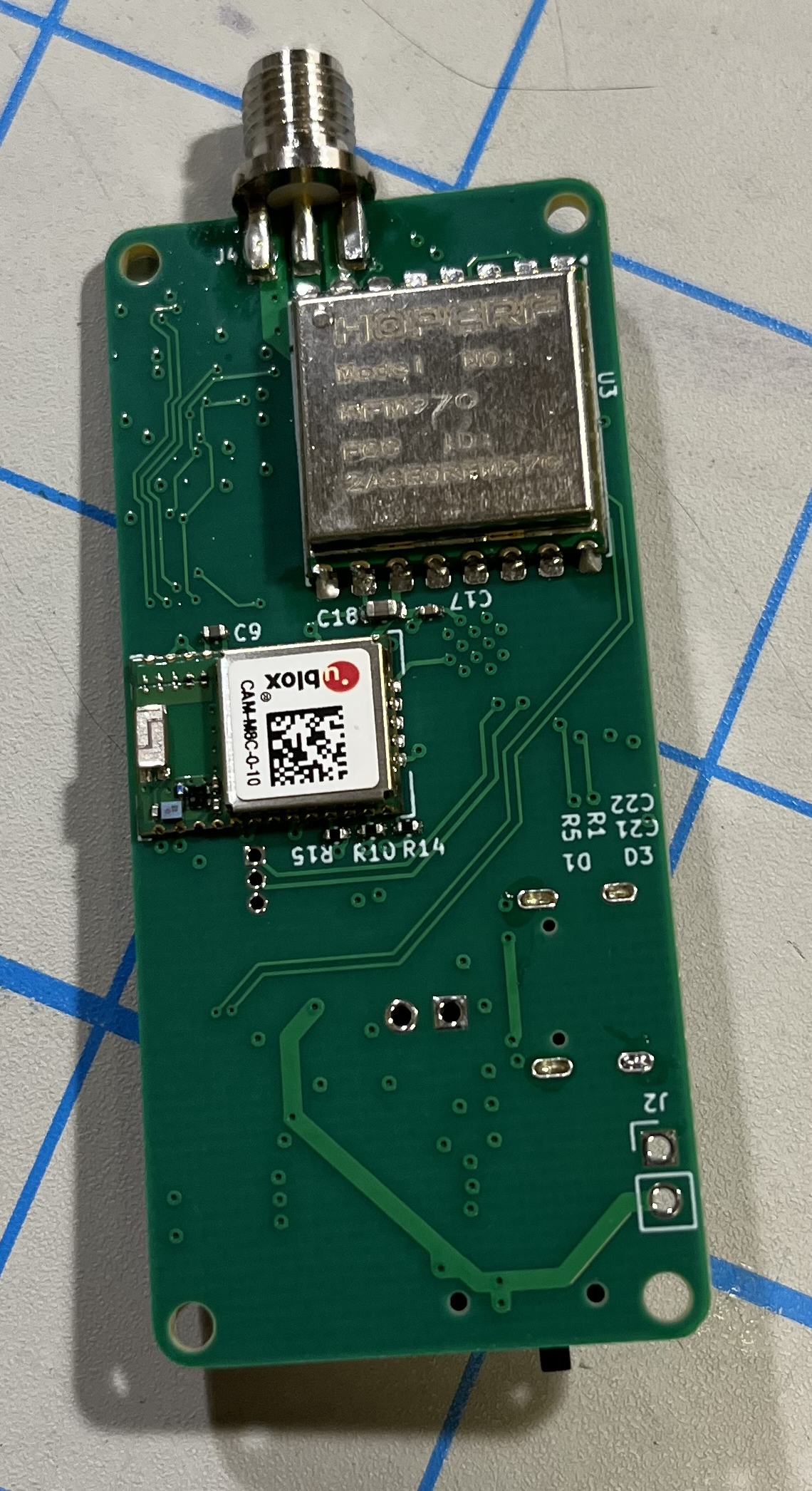
While designing this board, I tried to keep in mind how difficult it would be to manually place a bunch of tiny (0402) components and teeny ICs (like the magnetometer - EEK!), but I figured that I could handle tiny components, and the space-savings from using 0402 components and small-package SMD ICs would be worth the assembly nightmare. I don’t know how I would fit the same amount of functionality into the same form factor without making this compromise. Anyways, this time I ordered my stencil to be electropolished, because in the past I’ve had issues with inconsistent solder paste application, and with the pad spacing of some of the components I’m using as small as 0.2mm, I was really afraid that any slight solder-paste defect (bridging, etc.) would be a rework nightmare. This time I was also especially careful to make sure that the stencil was perfectly level and aligned to the board to ensure even paste application and prevent “splooge”. Conveniently, the manufacturer I ordered the PCBs from this time (NextPCB) sent the stencil attached to a rigid aluminum frame, which was super helpful (I think a lot of the issues with stencils I had in the past were because the floppy thin stencil would bow without support on the edges). After applying the paste (which surprisingly I got spot-on first try) I started the laborious task of placing all 64 (what a nice number!) components on the board, well, at least the front side . I started with all of the important ICs, then the passives, and finally the connectors and large SoMs (ESP32, GPS, etc). I baked the front side of the board in my reflow oven, the pasted the other side and soldered that using hot-air reflow.
Board Testing
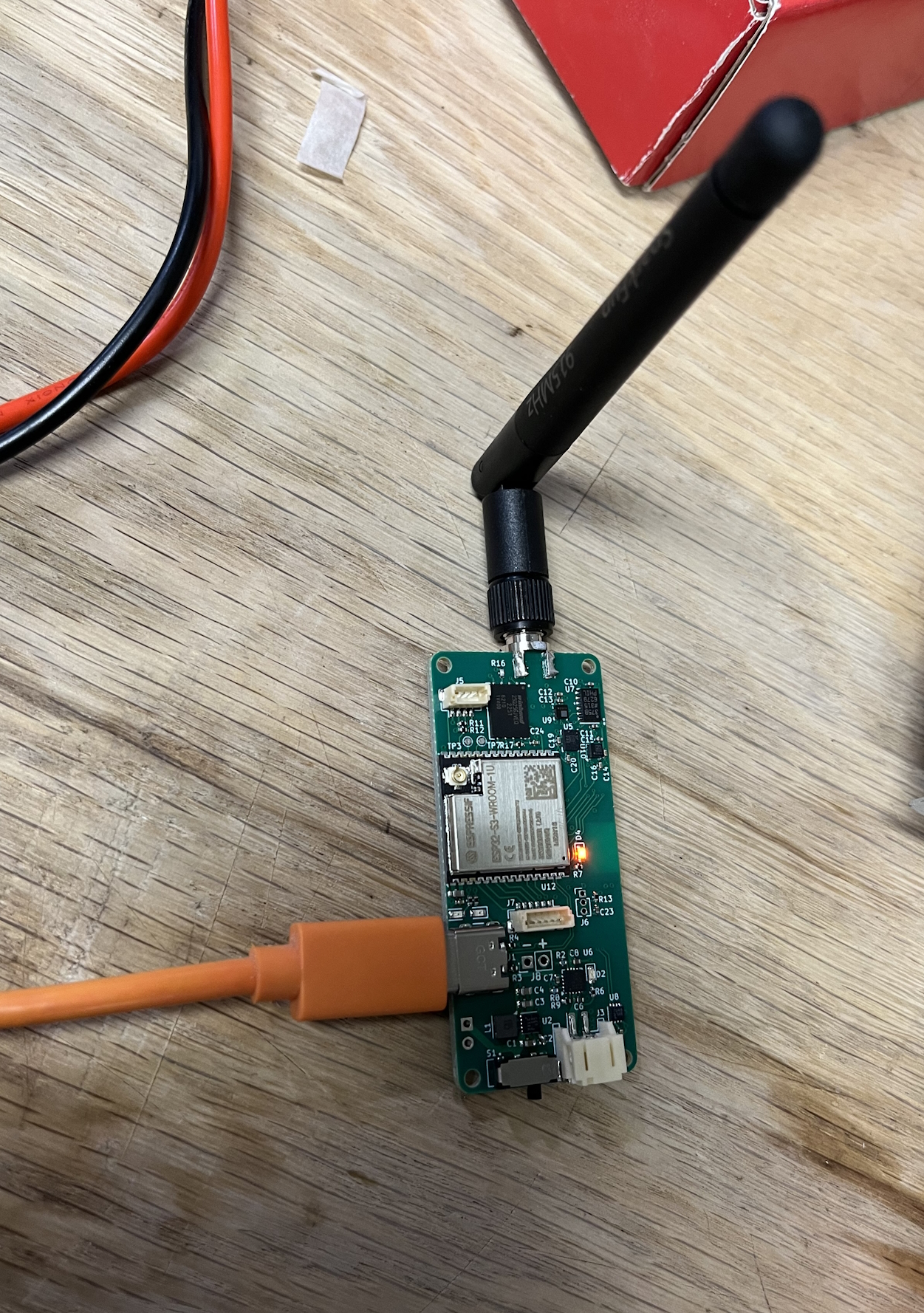
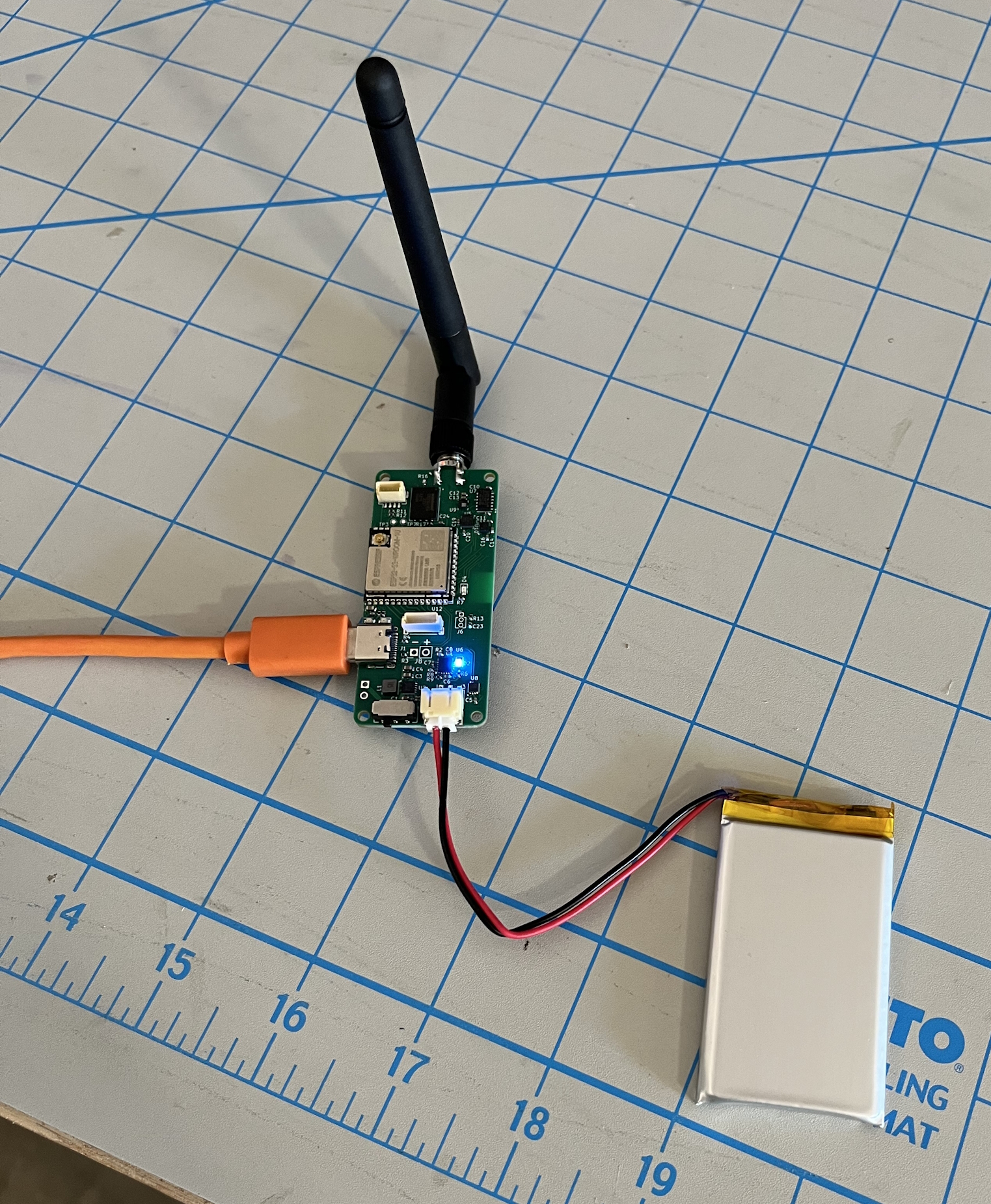
One of my biggest concerns for this board was the power system - I’ve never designed any battery-powered device before, let alone something with a charging circuit. The first big test was to plug in the board and make sure the board was getting a steady 3.3v supply. I didn’t want to risk my laptop, so I powered the board with a wall-wart, and, well, it seemed to work! No magic smoke, no hot ICs, all seemed to be good, and the components were all getting a steady 3.3v. I left it plugged in for a while and did some other things, and to my delight, when I got back the GPS 1-pulse-per-second LED was flashing! The GPS seemed to be alive and well. I decided to give the charging circuit a try next (eek! scary LiPo batteries!). I powered the board through a USB current monitoring device and hooked up the 1200mAh battery. The charging LED turned on and the board consumed roughly 500mA of current. The charge current for the battery should be set to 500mA, so I was pretty happy with the result. The battery also refrained from catching fire - that’s always a good thing. To test the rest of the components, I would need to get some firmware running on the ESP32.
Firmware Shenanigans
For programming the tracker, this time I decided that I would bite the bullet and write the firmware in plain C using ESP-IDF, rather than using fancy, complicated toolchains like PlatformIO or Arduino. (As I’m writing this blog post on 8/1, I will say that I do not regret this decision at all. At first it was a bit painful and a great learning experience getting all of the basic stuff working, but from then on, using ESP-IDF has made many aspects of firmware development much easier and simpler).
Just for reference, here’s a list of the firmware deliverables that I was aiming for on the first test-launch of the tracker:
- Sensor support (of course…)
- Unified USB & LoRa communications
- Versatile logging & easy log download
- 1Hz GPS and altitude telemetry
First of all, I started out my firmware based on the i2c_tools example, because I wanted to test the i2c-connected battery monitor IC. When I first plugged the board into my laptop I was a bit confused because it was making the USB-disconnect noise over and over again. I quickly realized that this was probably just the brand-new ESP32 rebooting over and over again, so I put it into bootloader mode and that fixed the issue. The board successfully flashed over USB (it’s really nice how the ESP32-S3 supports USB programming out-of-the-box). Running i2c_detect, I could see the battery monitor IC was visible on the bus, and using i2c_get, I could read the battery state - great! - another component tested.
Firmware Beginnings
The next components that I wanted to get going were the 3 ST-MEMS sensors on the board (LPS22 pressure sensor, LIS3MDL magnetometer, and LSM6DSM gyroscope+accelerometer). I had previously thrown together a prototype using a ESP32-S3 devkit and I2C breakout board of the LSM6DSOX, and while programming that I found ST’s platform-independent drivers. I’m really happy with ST for providing such great support for their components through these drivers - they are super easy to use and are part of the reason I chose to go with ST sensors. On this tracker, the sensors are connected via SPI rather than I2C (which I used in my prototype), but implementing the IO portion of the driver is really straightforwards. After a good bit of fiddling around with the intricacies of ESP-IDF’s SPI driver, I got the LPS22 driver working, and after that, integrating the other two sensors was as easy as copying the driver code and using it in the firmware (all of the sensors share the same IO functions). I also found a driver for the battery monitor IC, ported it to ESP-IDF, and added that in.
Radio Stuff
For the radio (still a RFM97CW, which is really, as far as I can tell, Functionally the same as a Semtech sx1276 LoRa transceiver) I decided to take another look at publically available drivers. Although I have wrote my own driver, I did so during the development of firmware for the receiver and it ended up getting pretty tightly integrated into how interrupts and DMA works on the RP2040 (I didn’t do a great job of making it platform independent), additionally, it’s just not a great driver. Looking on the ESP-IDF components registry, I found an existing sx127x driver that was exactly what I was looking for (no fancy bells and whistles, just a thin layer over the radios functionality). Using this driver, I was able to get the radio transmitting in a matter of about 30 minutes, way less time than I expected it would take, which was awesome. A working radio was great, but the majority of the communications work was yet to come.
Protocol
With the radio working, the obvious next step was to make a protocol to abstract radio communications for various functionalities across the board (telemetry, commands, configuration, logging, etc.). In the previous revision of the tracker, communications was made up of frames containing a header (ID and checksum), followed by a number of “datum” (8-bit type, 8-bit length, and data bytes consisting of a serialized protocol buffer). I still really liked this protocol (especially the protobuf part, it makes writing support software so much easier) so I decided I’d keep the general concept but make a few changes. First of all, this previous protocol was only designed to fit the 256-byte maximum payload length of the LoRa radio. In this new version of the tracker, I was planning to add USB communication support, which isn’t restricted to 256-byte frames. Especially for my plans to be able to download the log over USB, it would be really helpful to have larger maximum frame sizes over USB. To accomplish this, I changed the 8-bit length of each datum to be 16-bit, a pretty minor change, but enough to break compatibility. While thinking about how to make communication over LoRa v/s USB seamless, I thought that for USB, I would use the same format used by the receiver over USB serial. That way, it would be pretty easy to support both communication modalities from a support-software point of view. For transmission over a physical layer with packetization, each frame is sent using a hardware-defined frame. For transmission of frames over an interface without packet boundaries (such as USB serial), a simple escape-based encoding is used to encode the packet data, and one byte value (in my case, 0x00) is reserved for denoting packet boundaries.
Logging
One of the major goals I had for this version of the tracker was to be able to have high-resolution logging of all of the sensors built in to this device. On this device, the log memory consists of a single 16MB SPI flash memory chip. Conveniently, ESP-IDF provides a API for accessing generic SPI flash memory, which made actually interfacing with the memory (reading, writing, and erasing) very easy. Anyways, on to how logging actually works on this tracker. When I was thinking about how to format the logs for storage on the flash memory, my primary concerns were speed (specifically, worst-case performance) and wear leveling. Initially, I looked into using a proper filesystem. I looked at SPIFFS, LittleFS, and basic FAT, although all of those options have wear leveling, none of them are designed for real-time performance and have really bad worst-case performance (especially for appending to large files), so all of those options were a no-go. Initially I considered just writing the log linearly from the start of flash memory, but that obviously wouldn’t be good for wear on the memory. An obvious extension of this, and one that would fulfill my requirement of wear-leveling was to treat the whole flash memory as a ring buffer. Raw data from all of the sensors (in the format output by the sensor) is written to the log buffer in a standardized log frame format, in addition to a timestamp. GPS and other information is also recorded.
Log control & automatic logging:
On the tracker, logging can either be turned off, logging at a specific rate, or automatically logging based on flight state. Logging is controlled through a specific set of messages (datums) that can be received over either USB or LoRa. Logging at a set rate is accomplished through an ESP32 timer, rather than a FreeRTOS task, which makes logging timestamps more consistent. Automatic logging is based on a simple finite-state-machine that has three states: armed, liftoff, and flight. The tracker starts out with logging turned off (logging data at 0hz), and using a command, the automatic logging state machine can be started by placing the tracker into the armed state. Once in the armed state, the tracker logs at 10Hz until it receives an activity interrupt from the ADXL375 accelerometer (configured when acceleration exceeds 4g). Upon receiving that interrupt, it immediately transitions into liftoff state, where data is logged at 200Hz. After a 10 second timer, the tracker transitions into flight mode, where data is logged at 60Hz. The tracker then continues to log data at 60Hz until it is stopped using a command.
Detour: CLI tool
During the development of the communication protocol between the tracker and a computer over USB, I realized that I needed a better way to communicate with the tracker than the software that I wrote last year for displaying telemetry information on a map. I decided that it would the most convenient to make a simple CLI tool rather than a fully fledged GUI app to interface with the tracker because it would be significantly easier to develop, and would make adding new features much easier. Although I had already implemented the bulk of the communication protocol in last year’s GUI software, I decided to completely scap it and reimplement the protocol with a much more versatile interface that would. Currently, the CLI tool includes commands for a number of functionalities:
- Displaying the stream of telemetry information being received
- Starting logging manually
- Arming automatic logging
- Stopping logging
- Querying log size
- Downloading logs
- Erasing the log memory
- Fully wiping the log memory
- Pinging the tracker to test the connection
Log Downloading
The most complicated part of the logger is probably the log download process. I decided that it would be convenient to download logs using the same protocol/interface as the rest of the application, earlier in this post I mentioned the change from 8 to 16 bit lengths in the protocol, which allows for larger messages, but due to practical limitations (USB buffer size, etc.) it still doesn’t allow for messages long enough to contain an entire log. To circumvent this limitation, the log is transferred with a number of blocks that are 4096 or less bytes each. To download a log, first the CLI tool sends a message to stop logging if the tracker is currently logging. Next, the CLI tool sends a message that initiates a log download operation. The tracker then switches into log download mode and starts to send chunks of the log which contain up to 4096 bytes of data along with a CRC16 checksum, and information about the start and end address of the data in the log itself. After all chunks have been sent by the tracker, it sends one additional message containing any errors that may have occurred during the log download process, in addition to the XOR of the checksums of each chunk, which is a quick and easy way to check the integrity of the received data. Currently, the log data is stored as a python .pickle file for convenience.
That’s it for this post! In my next post I’ll explain the testing I did in preparation for this device’s first launch, some bugs that I fixed, and mounting of the device in the test rocket’s electronics bay.
Thanks for reading!