Rocket Tracker Part 6: Base Station Software & Tracking
In the time since I was working on the receiver in the last post I’ve been simultaneously working on improving the tracker firmware and developing the user-end software for viewing telemetry from the tracker in real-time.
Finding a Framework
I had pretty much already decided that I would use Python for the user-end software after trying to make user-end software in Rust lasy year which was fine, but had a lot of room for improvement. My hopes were that Python would make it relatively easy to support the software across platforms and also save development time. One problem though… I still didn’t know what GUI system to use! After doing some initial research I narrowed it down to Tkinter and PyQt (solely because they were the only GUI frameworks that I find map-drawing infrastructure for). The first steps I took to narrow down my decision to one GUI library was to get a map display working with both GUI libraries, as this was my primary concern.
Setting up a basic map display in Tkinter was quite straightforward thanks to TkinterMapView and the closely related CustomTkinter. Although displaying a map was easy, I don’t really like the programming style and GUI aestetic of Tkinter/CustomTkinter. On to PyQt! Setting up a map view using PyQt was a bit more involved, I found a few different libraries that provided map widgets and set out to test Folium and pyqtlet2. After spending a while trying to get QtWebEngine to work at all, I eventually managed to test both libraries and decided that I would use pyqtlet2 going forwards due to the ease of editing and updating the map display with it.
Getting Started with the GUI
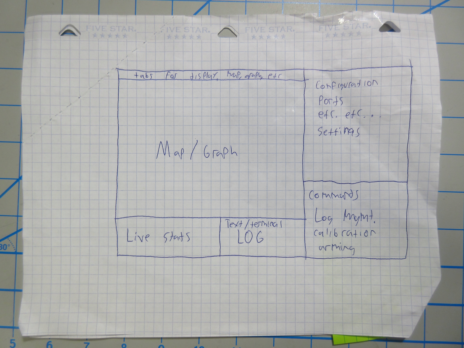
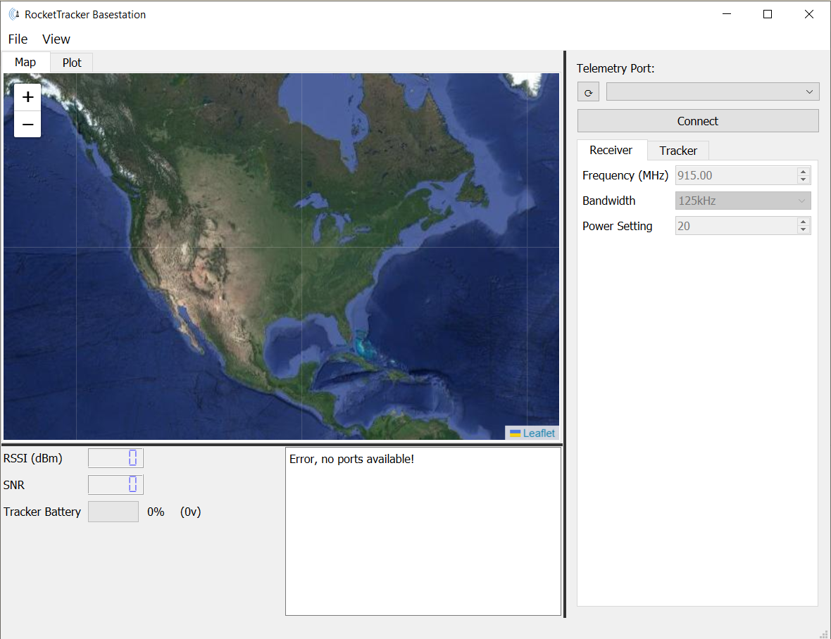
Now that I had decided on a framework (Qt) to use for the user-end GUI of my rocket tracker, it was time to get started laying out the UI. To start off, I made a rough drawing of how to organize the main components of the UI (map display, live stats, application configuration, tracker configuration, and receiver configuration) into four panels in the window. Luckily since I chose to use Qt, going from the design drawing to a workable UI was quite easy using qt-designer (pyqt5-tools designer) which can graphically edit qt .ui files that can be “compiled” into useable python classes with the UI compiler (pyuic5). Laying out the Qt Widgets took me about a half hour and after a bit of research I was able to launch the window from a python script and manipulate the widgets. Now that I could update the UI, it was time to start getting data from the tracker! To receive messages from the tracker I used the conveniently built-in QSerialPort of Qt and wrote a parser for the intermediary format I had devised to transfer data between the receiver and a computer. After doing this I realized that the intermediary protocol I had devised would be insufficient and unreliable due to the fact that there was no way of knowing where the start or end of messages were supposed to be…

A Better Intermediary Format
As I set off to create a new protocol between the receiver and the user-end software, I knew I would need a more reliable format for the messages so the user-end software could easily and reliably discern packet boundaries. Accomplishing this was pretty simple, but ended up being a bit tedious and annoying to test due to having to update both the receiver firmware and the python software. The easiest solution I came up with was to use zero bytes to start and terminate each packet. The advantage of this is that in the receiver firmware, receiving a zero byte would simply reset a FSM (finite state machine) that receives packets from the computer, and vice-versa on the user-end software receiving messages from the receiver. Unfortunately, the messages being received also inevitably contain zero bytes, how do I handle that? Well, it’s pretty simple. Using a certain byte value (I chose 0xFF) as a special “escape character” allows encoding zero bytes as a sequence of escape byte followed by another byte. I chose 0xFF 0x01 to signify 0x00, and 0xFF 0x02 to signify 0xFF (the escape byte itself). Tada! After re-working the FSM that received messages from the computer in the receiver firmware, I had the protocol implemented and tested!
Some Basic Tracker Firmware
After I got the receiver to talk nicely to the user-end software, I decided that I should probably throw some basic tracker firmware together so I would have some data to display on the GUI. I hadn’t touched the tracker in almost a year so refamiliarizing myself with the PlatformIO tooling and ESP-IDF API took a while. This problably warrants a future more specific blog post… Anyways, I got some basic features implemented:
- Ported the RFM97CW (sx1276) radio driver to the ESP-IDF SPI API
- Parsing the GPS data and sending it with the protocol I had devised
Displaying Stuff
Now that I have the tracker sending data to the receiver, and a means for getting the data to the computer, only one step left: parsing and displaying the data to the user. Initially, the only telemetry information coming from the tracker was GPS data. To parse the messages I created a mechanism that encapsulated a QSerialPort and parsed incoming messages, emitting a Qt signal every time a message was received. That way, I kept the business logic of parsing data from the serial port separate from the logic updating the GUI. For displaying the GPS data, I just used a marker on the leaflet (pyqtlet2) map and also created a line showing the path the tracker had traveled. After getting this working, I was ready to take the tracker for a test walk!

In my next post I will detail the issues I came across in testing the tracking setup, my solutions, and the continued development of the software and firmware in this project. Thanks for reading!