Rocket Tracker Part 5: Receiver Firmware
(And some basic firmware for the tracker!)
Since my last post about the rocket tracking system in which I detailed the assembly and basic testing of the receiver, I’ve been working on creating the firmware for the receiver and defining the protocol used for communication between the tracker and receiver.
Drivers
The first step in developing the firmware for my receiver was developing the drivers and infrastructure to interface with the hardware on the board, specifically the radio. The radio (HopeRF RFM97CW) contains a Semtech SX1276 LoRa transceiver which I had conveniently written a basic driver for last summer when I was working on the old prototype tracker and Raspberry Pi based receiver. Unfortunately, this driver that I had written had two issues: First of all, it was designed to be used with the Arduino framework so I would need to port the IO over to the IO functions of the rp2040 SDK. Before I found out about the second issue, I ported over the SPI communications of the driver to the rp2040 SDK, which wasn’t too hard since the rp2040 SDK is very well designed and easy to use in my opinion. While testing the driver by attempting to send messages between two receivers I found a second issue: the driver didn’t really work. Well, it worked in the sense that it correctly configured the radio’s frequency and successfully transmitted messages on the air, but the messages that were received didn’t contain the same data that was transmitted, or did they? Since I don’t have any other LoRa receiving or transmitting equipment I didn’t really have an easy way to tell if the transmitting or receiving function of the driver, or both, was broken. The first thing I did to debug the driver was to hook up my logic analyzer to the SPI communications between the rp2040 and the transceiver. On some analysis of the SPI transactions, it seemed like the issue was on writing the FIFO… annoying FIFO. After messing with the FIFO interfacing for both the receiver and transmitter for a bit I eventually managed to get it to work.
Better Drivers!
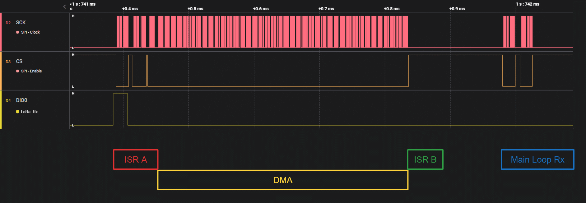
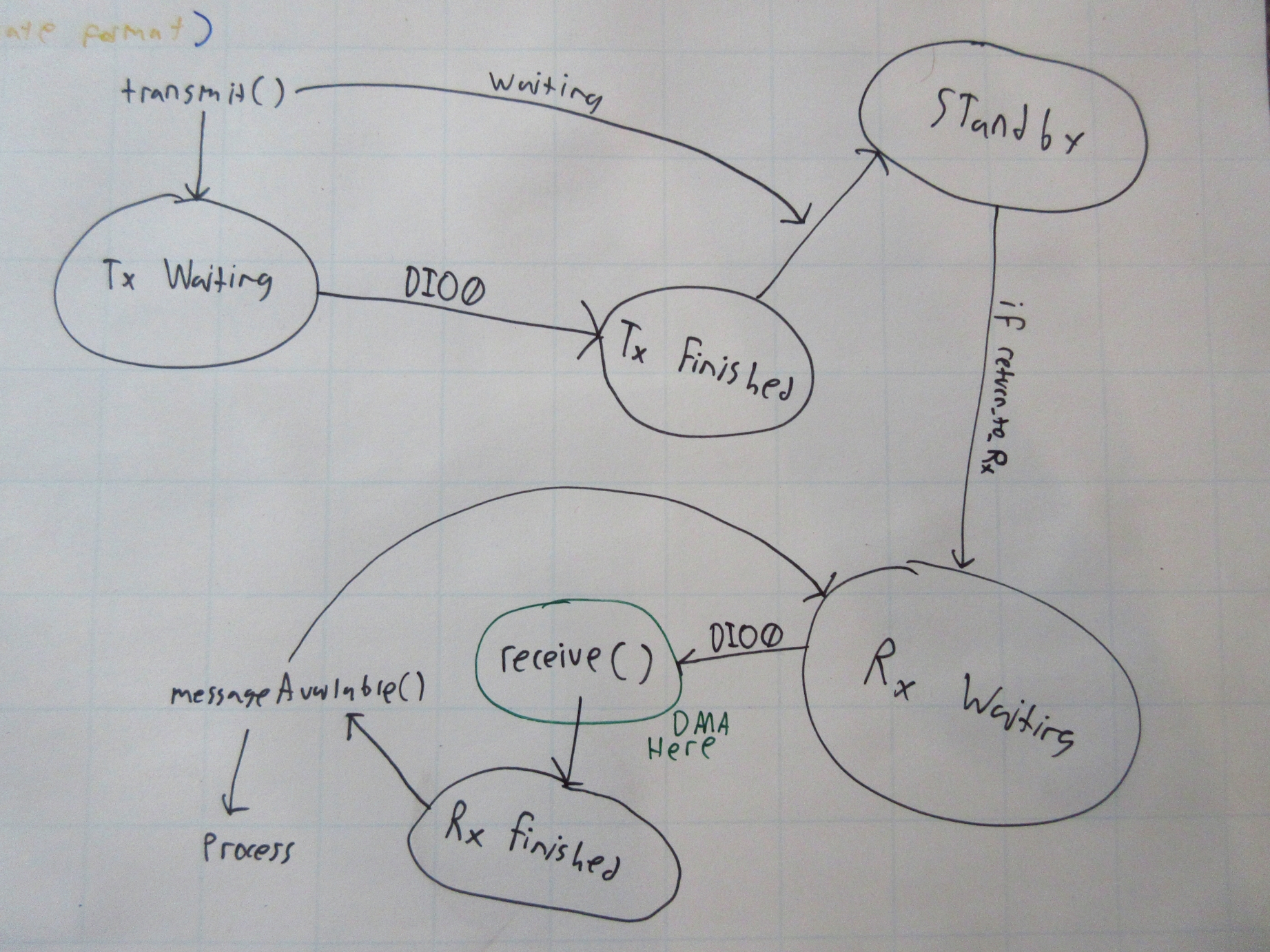
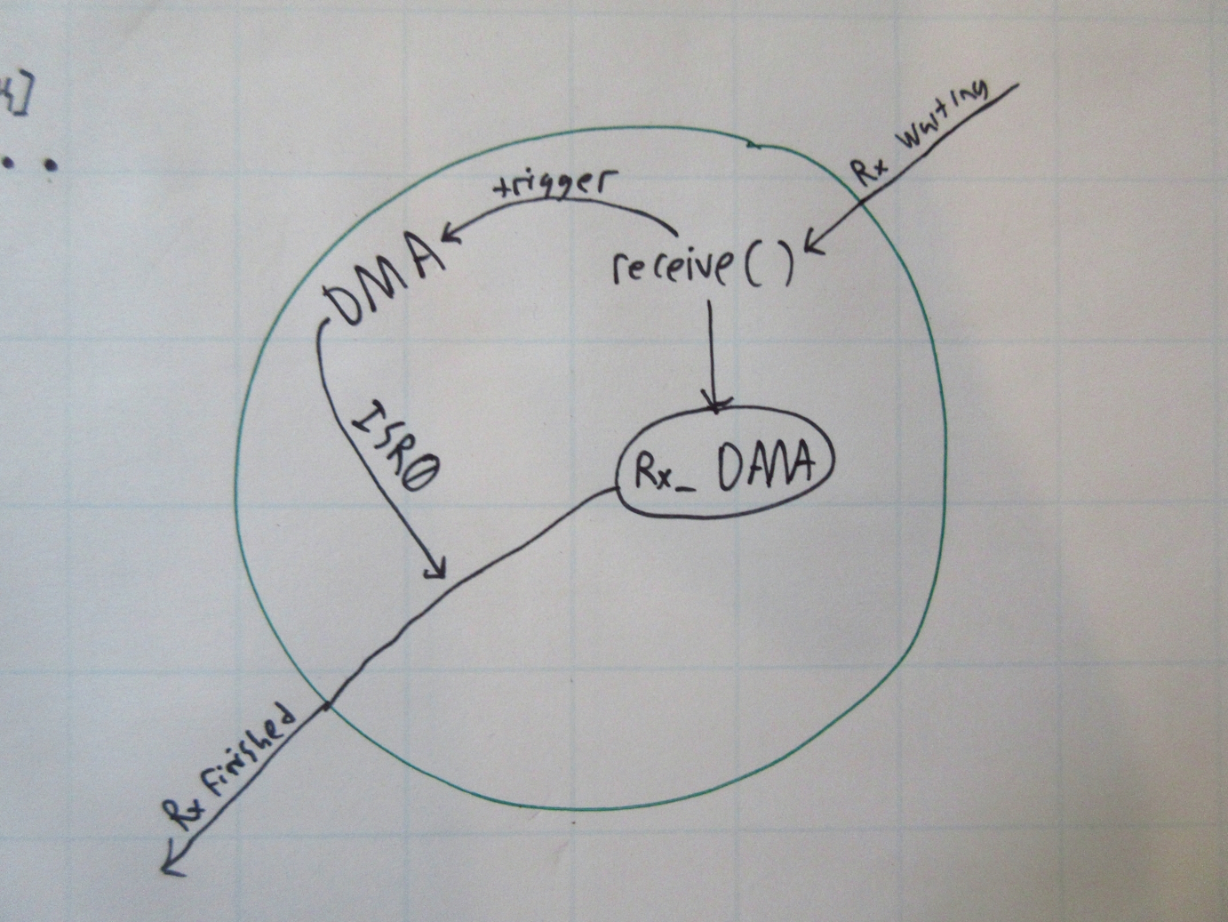
I’ve been looking for a reason to learn a bit more about DMA (specifically on the rp2040) for a while, and I’ve finally found a reason! Looking at the logic analyzer trace from the receiver I could see that the microcontroller must spend a lot of time waiting for FIFO transfers to complete while receiving and transmitting. To make matters worse, when the radio was transmitting a message the driver would wait until the transceiver was finished transmitting! Agh! What a waste of cycles! Stupid me… To solve these issues I made some modifications to the state machine of the radio driver to incorporate DMA and another interrupt routine for when a DMA transaction would complete. Reading and writing the FIFO with DMA ended up being a pretty simple task but as someone who hasn’t used DMA before it took me way longer than I wanted to get it working. As you can see in the diagrams below, the DMA transfer saves a lot of wasted time and was incorporated pretty easily into the state machine I was already using. ISR A is called when the radio pulls its interrupt pin (DIO0) high to indicate a message has been received. ISR A clears the radio’s interrupt register and starts the DMA transfer from the radio’s FIFO to a buffer on the microcontroller. Additionally, ISR A locks a rudimentary mutex for the SPI bus to make sure that the main program loop doesn’t break anything. When the DMA transfer completes, ISR B is called. ISR B releases the SPI bus, updates the state machine, and sets a flag to notify the main program loop that a message has been received. As you can see in the diagram, the main loop doesn’t have to do much, almost all of the IO is done asynchronously with DMA! The same goes for transmitting but the order of the ISRs is reversed since the DMA transfer’s completion is used to trigger the radio to send, and the radio’s DIO0 pin goes high when the transmission is complete.


Fun with USB
Now that radio communication is sorted out I can finally get to the implementation of the receiver as an interface between software running on a laptop or computer and the rocket tracker. I decided that the receiver would use two separate interfaces for software on the computer, both of which would be implemented as USB-CDC serial ports: A “Virtual GPS” port which produces NMEA-0183 formatted GPS information with the tracker’s position providing compatibility with the same software someone would use for another tracker such as an EggFinder. A telemetry port which relays the raw frame data received from the radio to the serial port, and sends raw frames from the telemetry port to the radio. To implement this functionality I needed more functionality than the default single serial port that the SDK makes available. To do this I needed to use TinyUSB which is used internally by the SDK. The most difficult part of getting TinyUSB to work was figuring out how to configure it. Unfortunately I couldn’t find much if any documentation for all of the different configuration variables, but the examples were pretty self-explanatory. After I had it configured the two CDC endpoints, set the buffer sizes, etc, actually sending and receiving from the ports was really straightforward. After implementing the functionality that I originally planned out I added some additional features including configuration of the radio (frequency, bandwidth, spreading factor, etc.) via NMEA messages on the GPS port.
Testing
To test the receiver I need a transmitter of course, I made some basic firmware for last summer’s prototype tracker but going over that is out of the scope of this blog post and I will certainly cover its continued development in a future post. I had tested communications between two receivers but I hadn’t tested the antenna and PCB of the tracker prototype yet. I went for a walk with the tracker transmitting and the receiver sitting in my garage connected to my laptop with MapSphere logging the GPS track. When I got back, I was happy to see that the receiver seemed to have logged the majority of my walk! I wasn’t expecting it to work as well as it did because I live in a densely forested neighborhood and the propagation of the radio’s 915MHz (VHF) signal should be affected by multipath propagation from houses and absorption by foliage. The furthest I was away from the receiver was a little over a half mile and even though that’s not super far I have confidence that the radio will perform much better in the environment that its designed to be used in (rocket launch sites with virtually constant line-of-sight to the rocket and high altitudes with no obstacles) and the antenna I plan on using for rocket launches (915MHz Yagi rather than the small whip antenna I used for testing)
Thanks for reading!