Making a Tiny Robot (Just for Fun)
As I write this post, I’m thinking about and working on building a little robot, mostly for fun, but also because I want to try to get it to drive in certain ways without encoders using only other sensors such as an IMU, etc.
Day 1: Design Considerations:
Drive Train
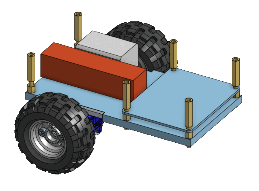
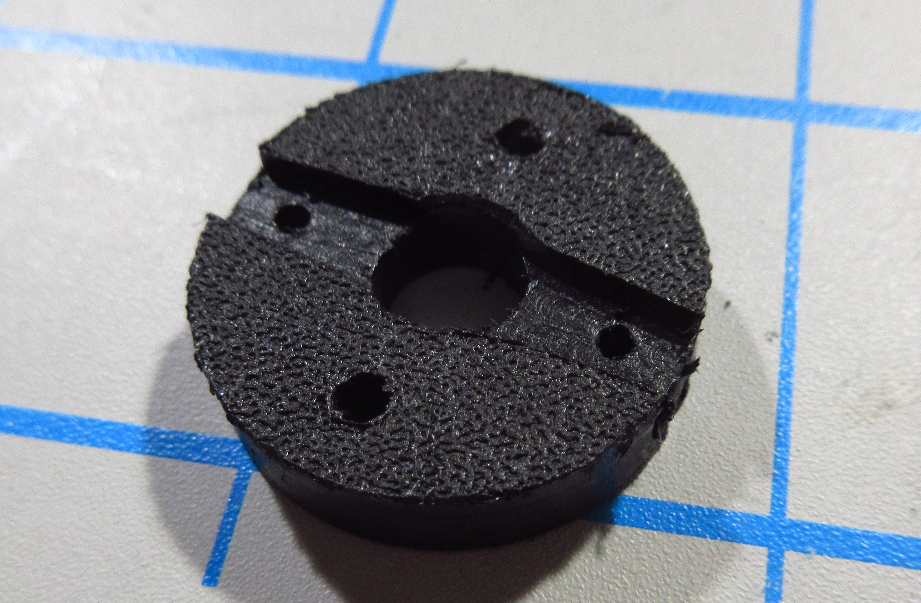
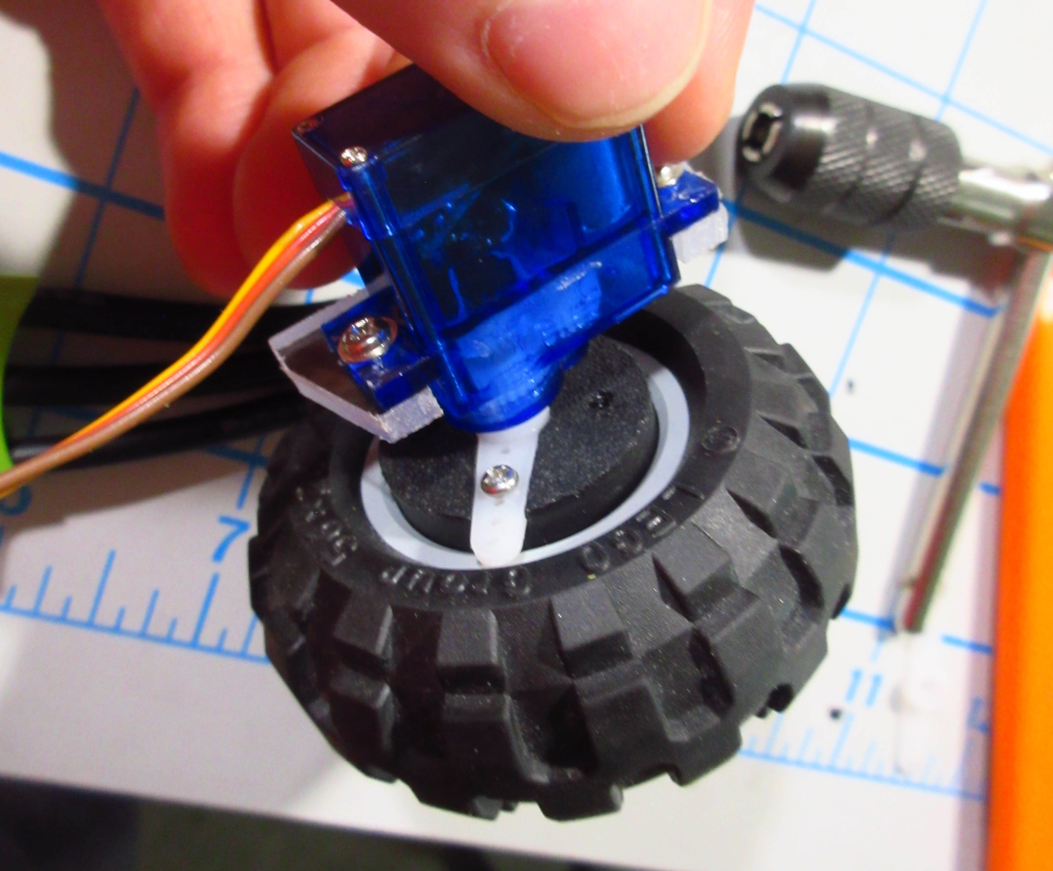
Part of the inspiration for making this tiny robot came when I took apart a sg90 servo for fun and decided I’d try converting it into a continuous rotation servo (replacing the potentiometer with a fixed voltage divider and removing a few mechanical endstops), so, obvoiusly, I’m going to use these modified servos as drive motors. In thinking about which wheels to use with these motors, I originally thought I would 3D print some wheels in ninjaflex, but after considering this for a while I eventually decided that using some lego wheels would be much easier than CADing and printing custom wheels from scratch. To attach these lego wheels I designed an adapter that I could CNC out of .22” HDPE that bolts to the servo horn and lego wheel.
Electronics
To control this robot, I thought I’d try to use a small self-contained development board that could run off the same 5v supply as the servos.
Pico W v/s Nano Every
I was tempted to use an Arduino Nano Every but I eventually decided to use a Raspberry Pi Pico W with the rp2040 MCU that I adore instead due to it’s WiFi+Bluetooth networking and my familiarity with it and it’s SDK.
To supply power to all of these lovely electronics I’m going to use one of my 550mAh LiPo batteries through a 5v, 3 amp buck converter which is probably overkill for the servos’ 360mA stall current, but I might need the extra current in the future for other peripherals. Speaking of peripherals, I am also going to add some sort of interface with a RC receiver and maybe in the future I’ll make room for some nice blinky lights too.
Frame Design
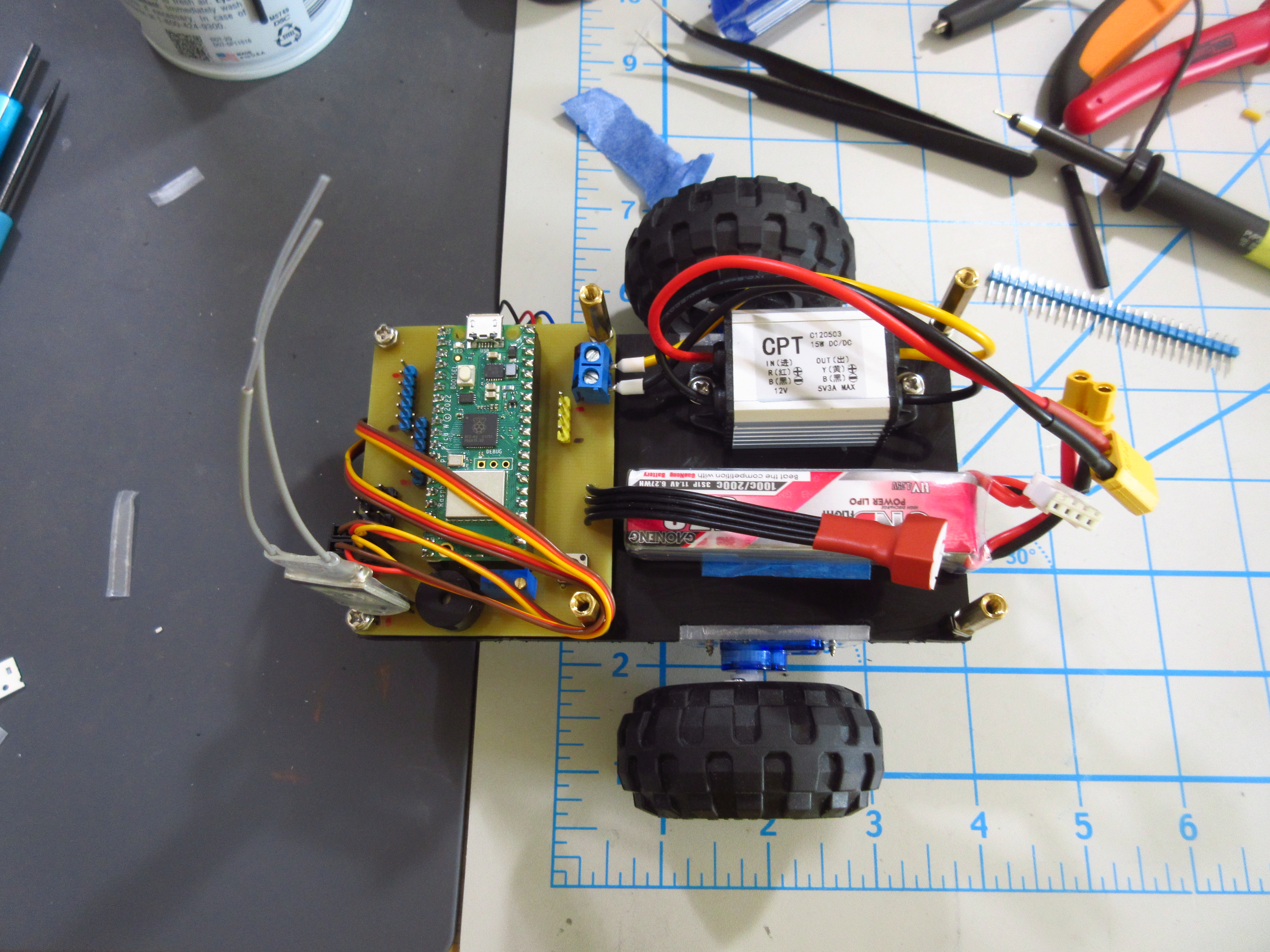
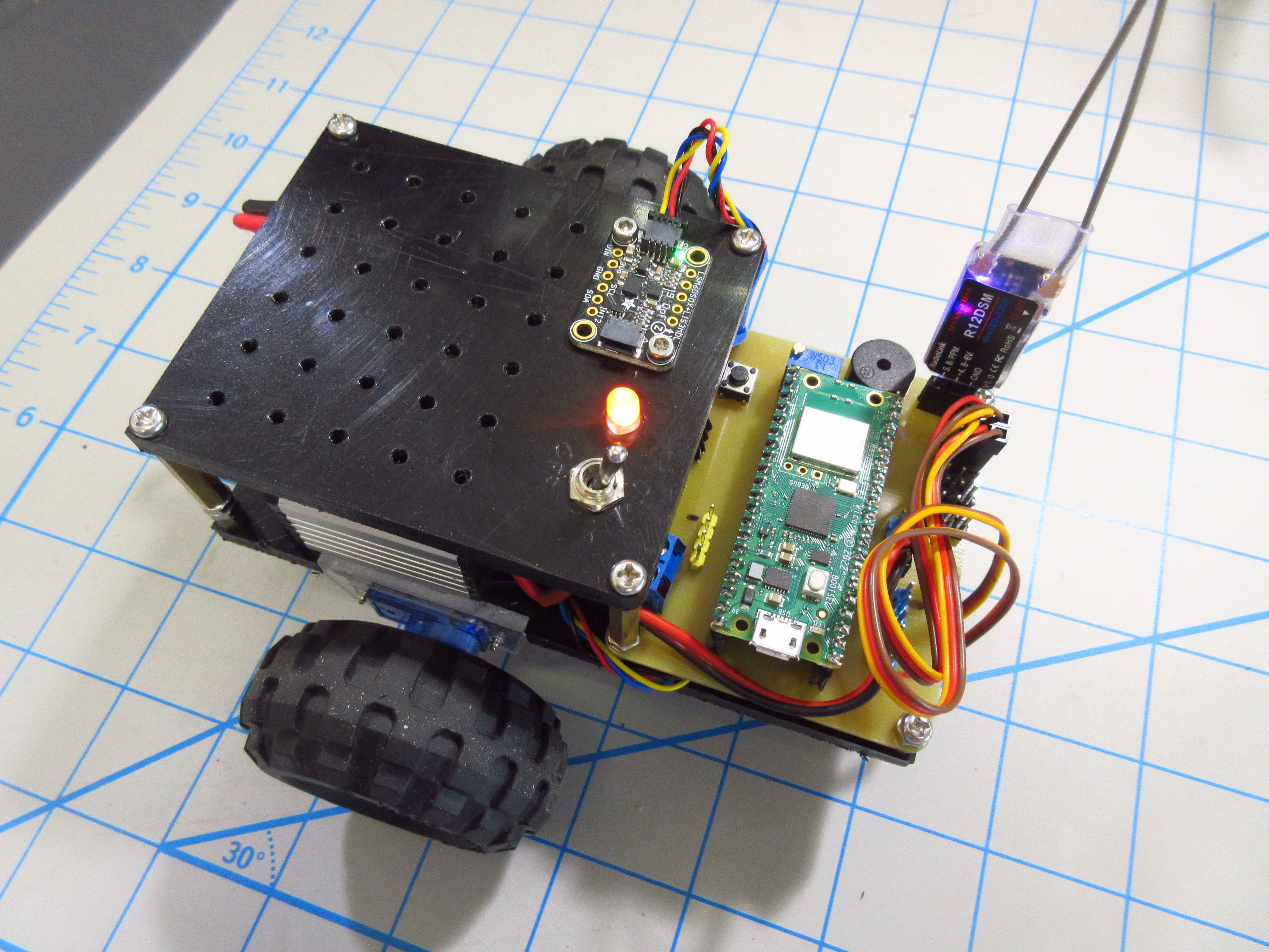
Wouldn’t it be convenient if I could fit all of this onto a single CNC machined piece of HDPE? Well, that’s the goal. Well, I got carried away making a PCB to hold all the electronics so this was designed a bit late. Aside from the lego-wheeled-servo drive modules mounted with polycarbonate brackets, the frame is a pretty simple HDPE plate. The control board and top cover are both mounted with M3 standoffs.
Day 2: Building the Bot
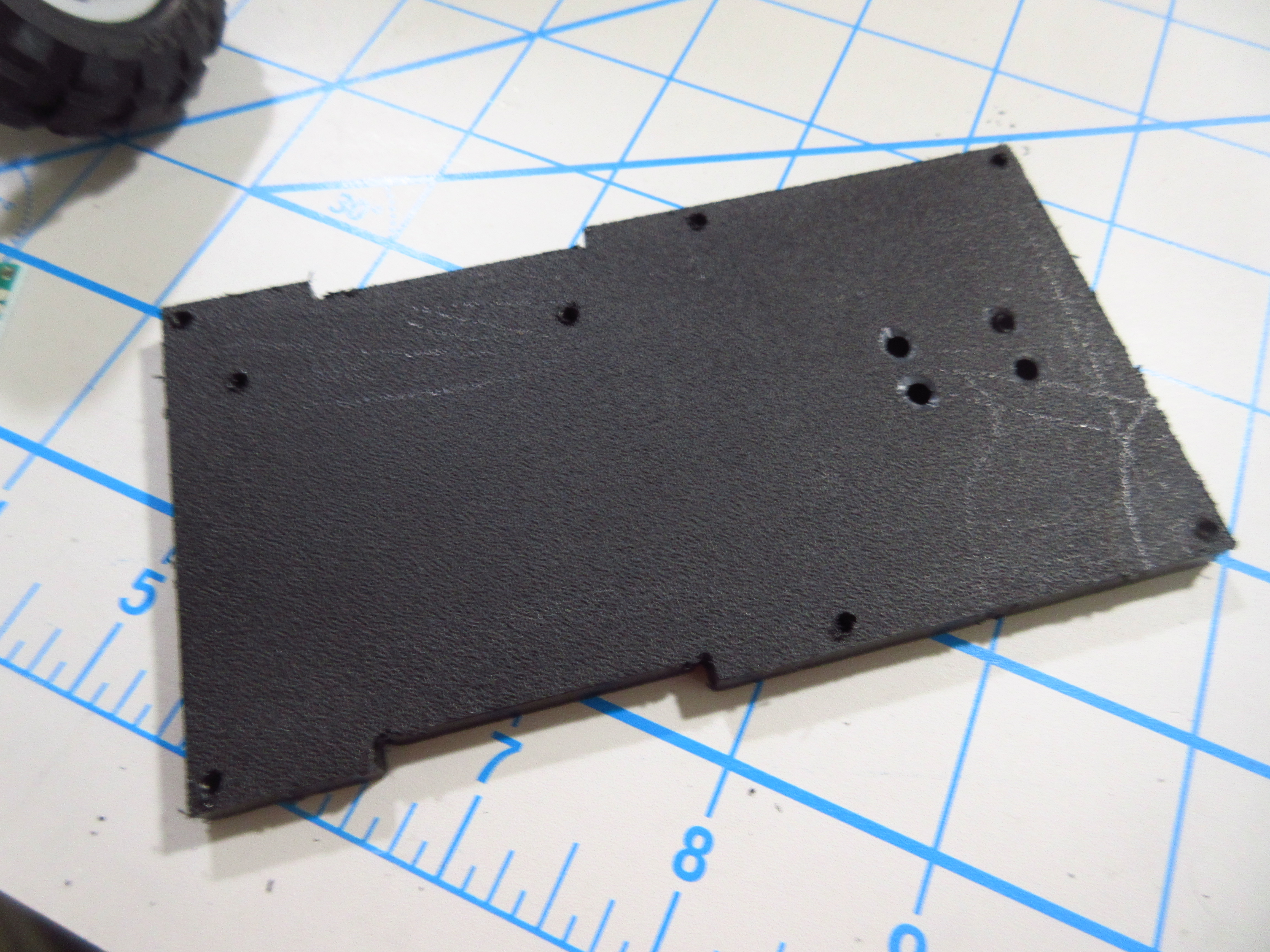
The first thing I did was to get all of the different CNC machined parts for the robot programmed (with fusion 360 as always). I CNC’d the servo mounts, wheel adapters, and baseplate for starters. After I’d cut all of the parts I need I glued the servo mounts onto the base and screwed in the buck converter
Finishing up the PCB
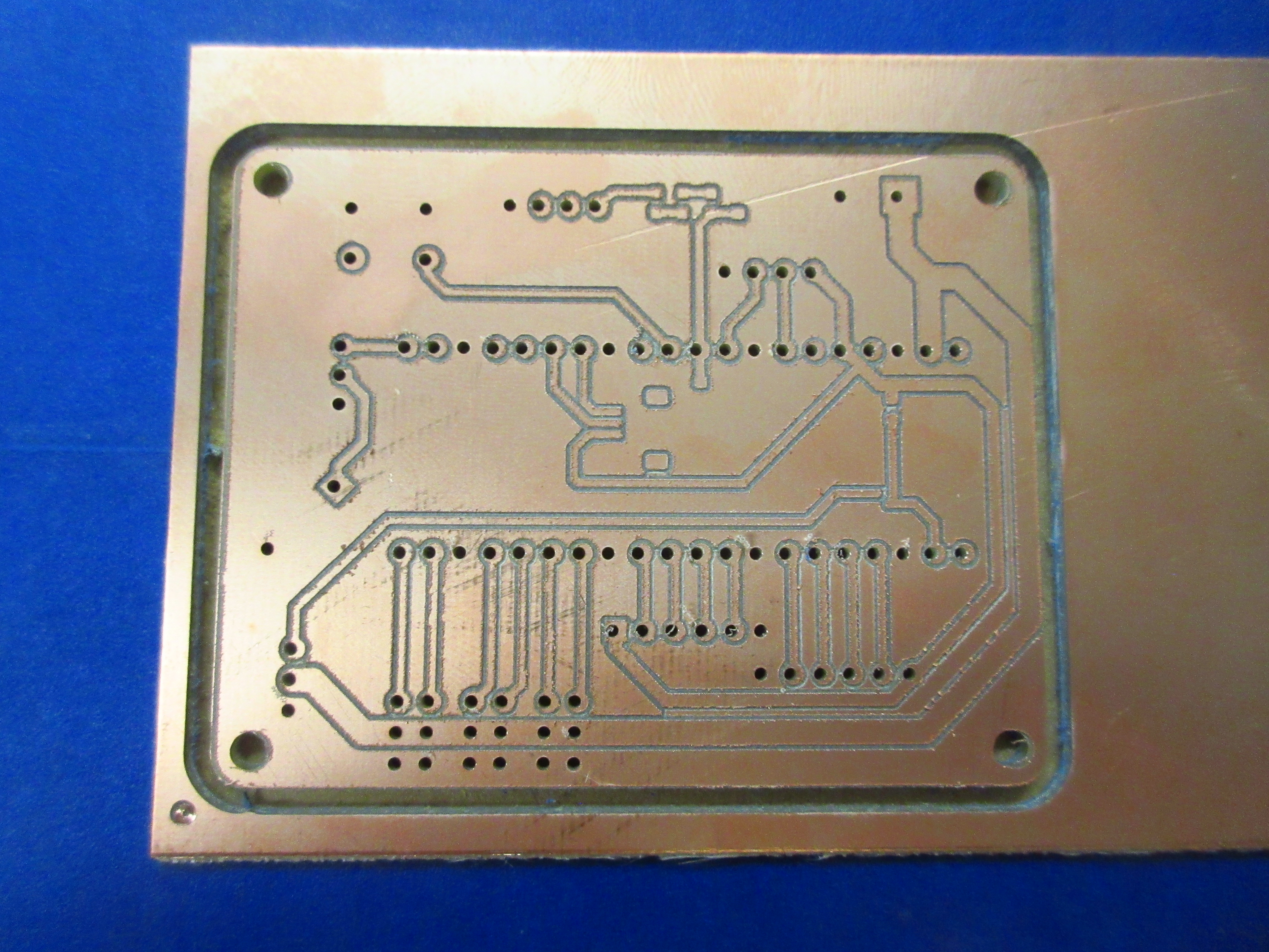
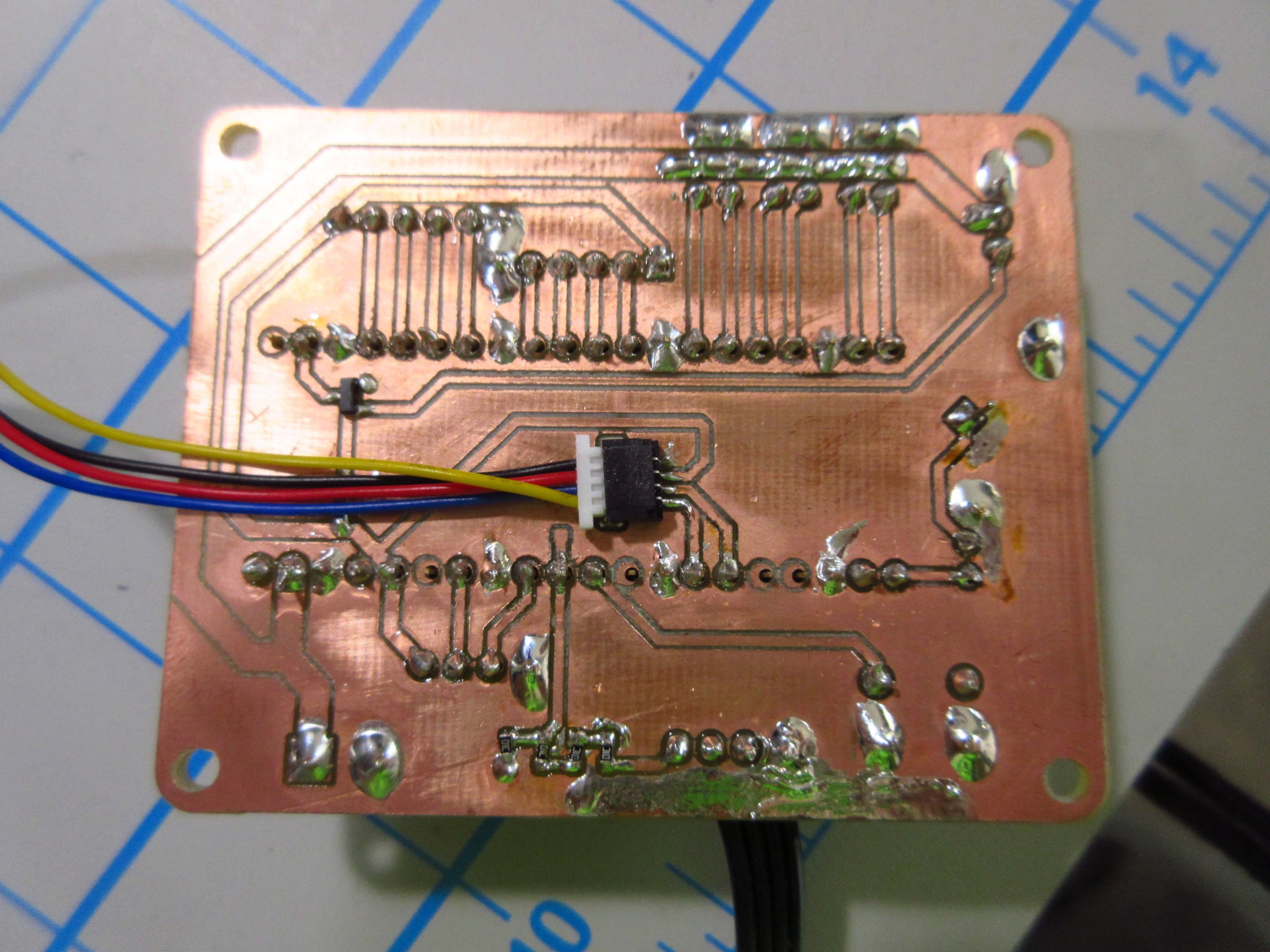
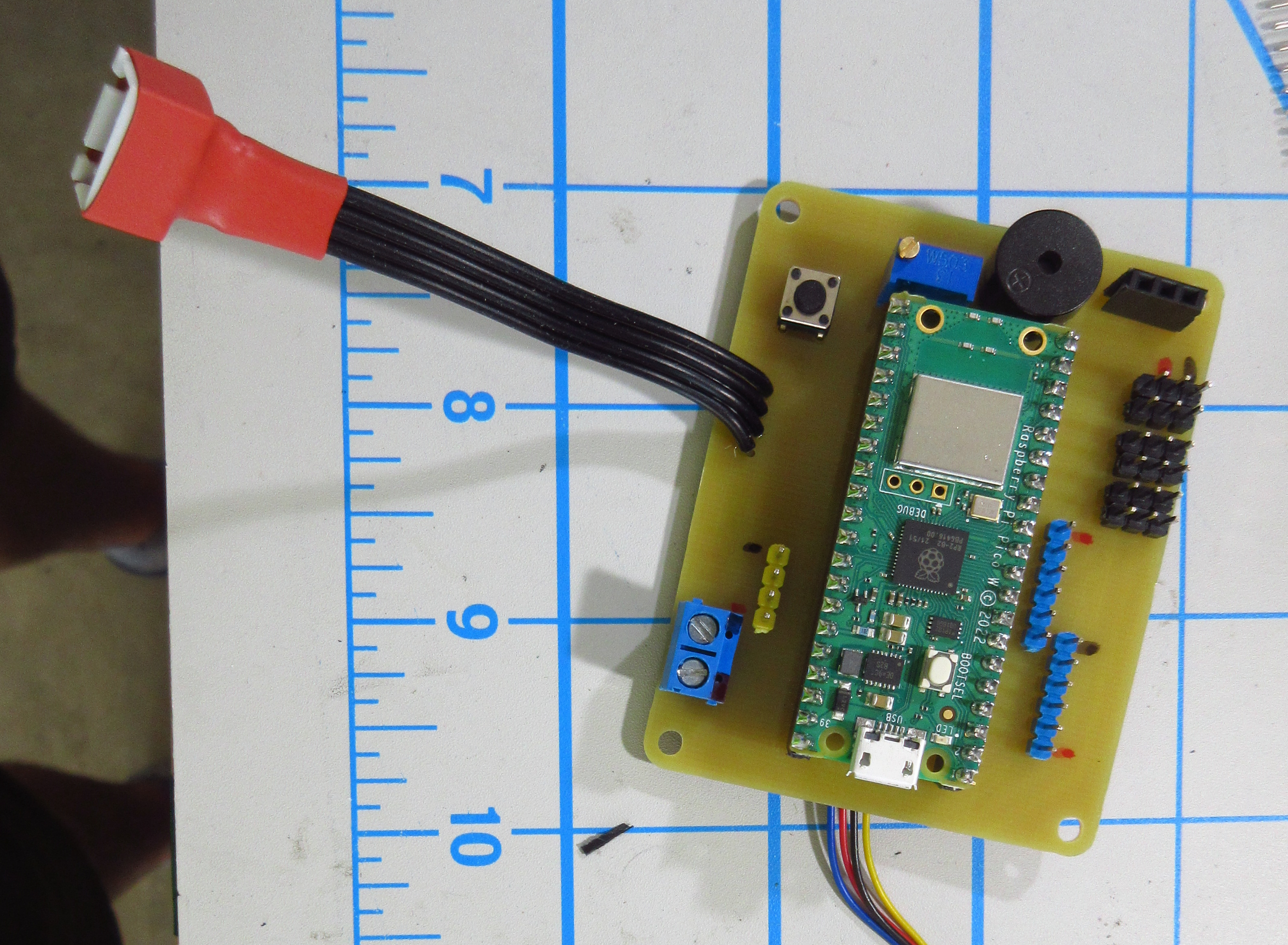
After the major mechanical components of my robot were done I resumed work on my control board from yesterday. After a while I had finished my PCB with the Pico W, piezo beeper, reset button, battery balance connector, 5v input, SBus RC receiver input, and last but not least GPIO + PWM breakout for servos and other miscellaneous sensors. For milling this PCB I decided to swap the RotoZip RZ1 router on my MPCNC for the Dremel 4000 I had previously mounted which is much less powerful but (I think) has less runout which would make for a cleaner circuit board. After using the masking tape and CA glue method to fix my bare copper clad FR4 to a piece of MDF everything was ready to go. After milling the board, I could tell that the dremel did indeed have much less runout than that of the RotoZip but the board still had some “fuzzies” but those were easily removed by some 1000-grit sandpaper.
Finishing Up
Assembling the PCB was pretty straightforward along with wiring up the buck converter and other minor electronics. Once was done with that, I powered it up and to my suprise, no magic smoke escaped! Since I had converted the servos to continuous rotation, I didn’t really know the proper pulse lengths and zeroing for the motors, so my first step in programming the robot was to zero the motor PWM. Identifying the zero-throttle pulse length of the motors proved to be a bit laborious but once I had tuned it in for each motor the value didn’t seem to change with the motor’s temperature which I was afraid of. To finish things up I designed a top cover for the battery with a hole pattern to mount future sensors and other bits.
Thanks for reading! I hope to make another blog post when I find a use for this little robot in the future.