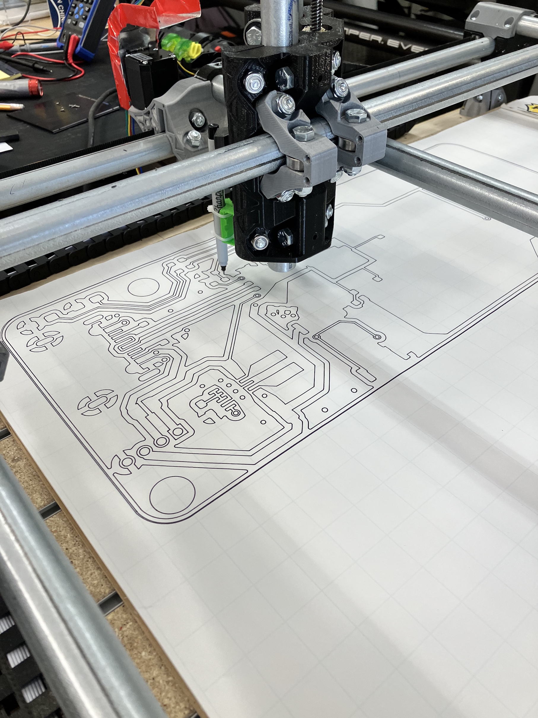
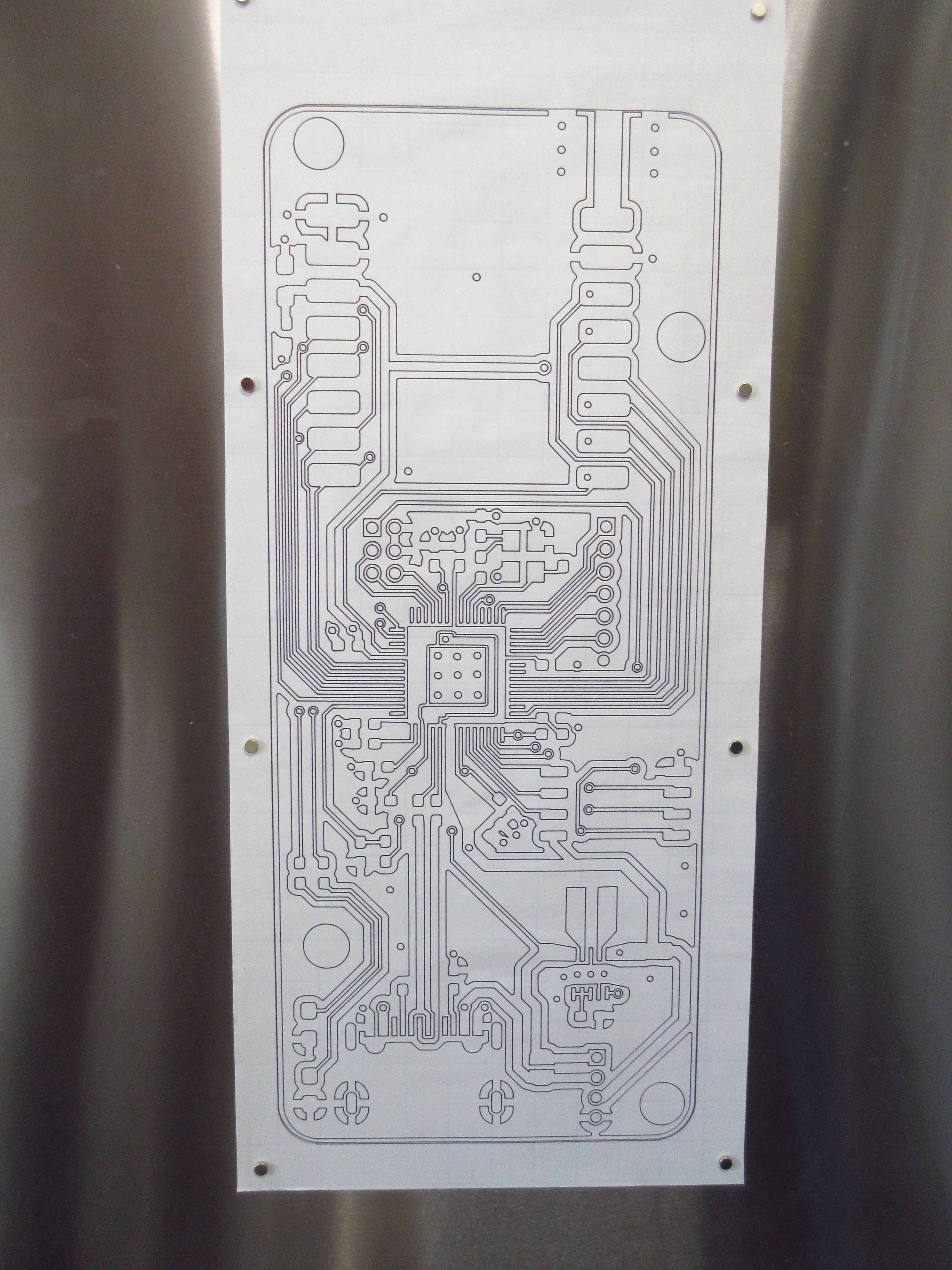
Rocket Tracker Part 3: Receiver Design
If you’ve read my last blog post you’ll know that I’ve been at work redesigning and rethinking the receiver for my rocket tracker. I’ve spent the last few weeks designing new hardware for this integral component of the rocket tracking system. After all of my work laying out, reviewing, and double-checking a new receiver PCB, it is with great pleasure that I can finally inform you that I’m broke! I just ordered all of the components, stencils, and boards for the receiver and I guess now is a better time than ever to explain the process and work that went into designing this new piece of hardware for my project.
Starting a New Design
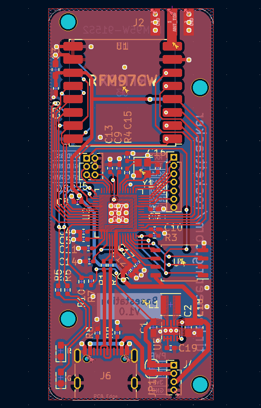
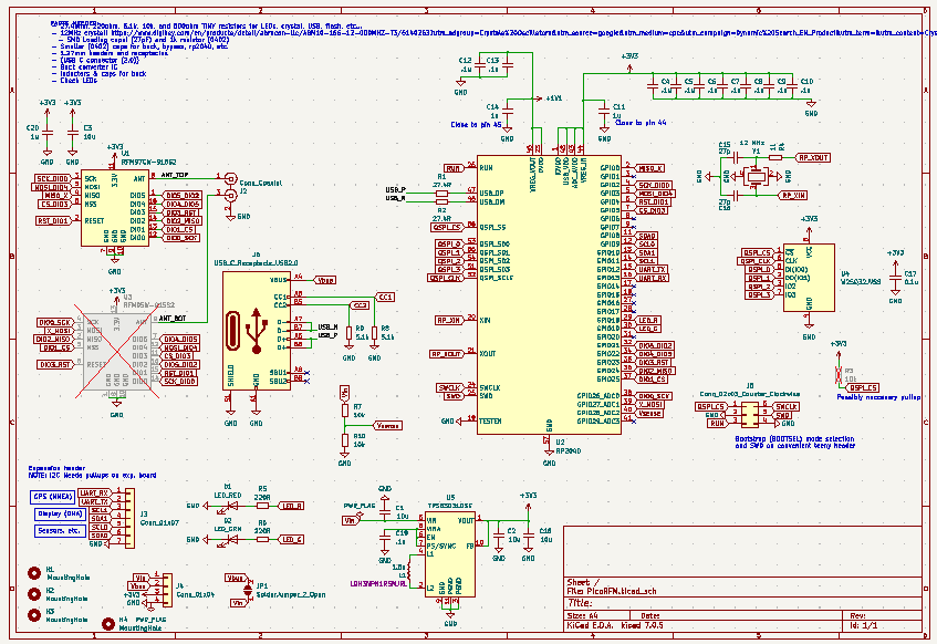
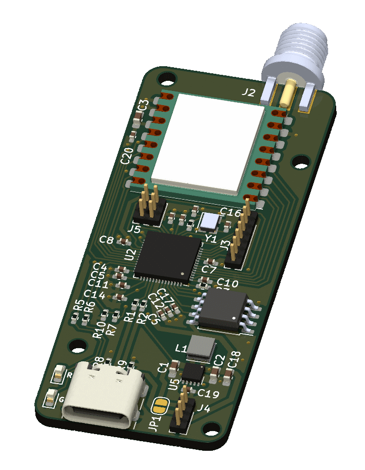
First of all it all started out with the idea of a new tracker that I went over in my last blog post. This new receiver aims to create a simpler and more minimal connection between the end user and the data being collected by the rocket tracker. To accomplish this the receiver has been reduced to a simple USB dongle, rather than a full-fledged computer running all of the back end software for the rocket tracker. Additionally this new receiver is designed with expansibility in mind and in the future I plan on designing an add-on board that would allow the receiver to operate as a handheld device that simply leads the user to where the rocket has landed, what could be more user-friendly than that! To start designing this receiver dongle I first need to decide on the major components and specify exactly what features I wanted this board to have. I decided to use the Raspberry Pi rp2040 microcontroller as the brain of this board because of its low price, built-in support for USB, ease of programming, and ubiquity among modern hobby projects and development boards. The other essential part of the receiver was the radio module which I had already decided would be a HopeRF RFM97CW radio module because I’m already using it on my first version of the tracker. At this point, now that I had decided on the major design considerations and components of my board, I was ready to get into the nitty-gritty work of designing the PCB and selecting other components for the design.
Design Details
Alongside these larger components, building a device like this requires many other smaller but still very important components such as power supplies, bypass capacitors and of course, connectors. One of the more painful aspects of designing a board with the rp2040 microcontroller is the fact that it requires not just one or two or three bypass capacitors, but 11 individual bypass capacitors that need to be placed in close proximity to the microcontroller. This led me to make the decision to finally use 0402 components, which are a bit smaller than the smallest components I had used previously, 0603 components, which are already just barely large enough to hand solder. Although it is probably possible to hand solder 0402 components, due to the large number of these tiny components, having a stencil is pretty much a necessity for PCB assembly which unfortunately adds more upfront the cost to even low volume production. For my initial design of the board I decided to use a USB-B connector that I had on hand, and a low dropout voltage regulator that I also had already purchased for another project. As I started to lay these components out on the board and began to Route them together I began to realize just how much space a USB-B connector and DPAK packaged voltage regulator takes up.After being dissatisfied with my initial design for the board I decided that I would reconsider the type of USB connector and power supply that I was using. Around this time I had the idea that it would be possible to design a dongle that could also be converted to a handheld device, and this handheld device would likely be powered by a Lithium-Polymer (LiPo) battery which is commonly used in this type of application. The decision to pursue this idea came with two major modifications. First the device would need to provide expansion headers or connectors to allow attaching another PCB on top or on the bottom of the dongle PCB, the largest component of this would be deciding what type and how many IO this expansion board would requireI eventually decided that the only interfaces that the expansion board would need would be two I2C buses and one UART. You might be asking why two I2C buses? isn’t it a multi-drop bus? To answer this question, yes I could use just one I2C interface, but my plans for the expansion board involve having multiple sensors and an i2c based OLED display. To reduce CPU overhead, it would be very convenient to be able to write to the display using the rp2040’s convenient DMA infrastructure, and to reduce additional software overhead for bus arbitration etc, it is much easier to have one I2C interface for the display (completely controlled by DMA), and another for the sensors (operated by the CPU). Secondly, the dongle would require another more drastic change: the power supply. the current power supply of my board was a low Dropout 3.3v regulator rated for 800 milliamps, with a Dropout voltage of 1.2 volts, LiPo batteries have a fully charged voltage of 4.2 volts, so even when fully charged, this voltage regulator would not be able to provide a full 3.3 volts to the rest of the board. To get the most out of a LiPo battery, I would need to either use a special ultra low Dropout regulator, or an efficient buck/boost converter capable of producing a steady 3.3 volts, no matter the battery’s voltage. I seriously considered going for an ultra low dropout regulator, because of how easy it would be to substitute my current power supply for it, but a buck boost converter is really the right choice for a LiPo power design since it can operate over the full voltage range of the battery, and produce a steady supply of power at high efficiency, increasing battery life. An additional perk of including a buck boost converter into this board would be that I could use the same buck boost converter used in this board to power future versions of my rocket tracker, which face a similar problem using a low dropout regulator with LiPo batteries. It’s also a good idea to include a battery charging or management circuit into devices that are powered by LiPo batteries, but I avoided having to add this circuitry to my dongle by designing the power connection to expansion boards in a way that would allow the expansion board to house this circuitry. Now that I was replacing my power supply, I decided to also replace the USB connector. These days it’s uncommon to find a USB-B connector in the wild, and if you do see one it’s likely part of an older device. Many modern computers, phones, and devices these days are moving towards USB-C (annoyingly, including my laptop which only has one USB-A port). So I decided that I would swap the USB B connector on my board for a more compact and more common USB C connector. Switching from USB-B to USB-C wasn’t too difficult, but it required the addition of a few extra components to support the USB-PD protocol (two resistors, I know, big deal) and the routing was a bit of a pain. Overall, I’m glad that I chose to make some modifications to my initial board design to make it more expansible and easy to use.
Radio Rework
Another thought that I had later on in the design process came along when I was trying to buy more radio modules. I found out that pretty much the only place I could buy these radio modules was from SparkFun, and they had implemented a five per customer limit on the specific radio module that I was using. That got me thinking about maybe switching to another radio module, but I decided that that would be too painful since it would require a redesign of the tracker as well. I did a bit more research to find out where I could buy other radio modules made by HopeRF which share the same form factor as the one I’m using. Unfortunately even though these other radio modules share the same package and footprint as the one I’m using, it seems like the radio module I’m using is the odd one out and all of the other radio modules seem to share a common pinout while mine has an annoyingly different, almost mirrored pin out, so to support these other radio modules on the same dongle, I would need to add an entirely different footprint where I could install one of these radio modules as a substitute for the current one I was using… and that would require a larger board… Wait, mirrored? couldn’t I just flip the footprint and put it on the other side? Well, yes in a way, and that’s what I eventually decided to do. the footprints for these other radio modules weren’t exactly mirrored, but at least the antenna connector was, so I decided that I would add the option to install a different radio module on the other side of the board in place of the RFM97 thatI intended to use in case they went out of stock. Unfortunately, since the pinouts weren’t exactly mirrored I couldn’t just route the signals for SPI and the radio’s digital IO right through the board to the other side, or could I? Thanks to the versatility of the rp2040’s IO, I was able to route most of the digital signals right through the board with only a few extra traces! Success! I think I have future-proofed my board at least for now.
The End.
Now that I was finally satisfied with the major design for my board, I went on to implement a few extra quality of life features including some status LEDs and circuitry for measuring the board’s input voltage, and at last, I was ready to order my board. Before I ordered my board though, I carefully went through my PCB layout, schematic, and gave all of the component’s datasheets another once-over to make sure I didn’t miss any major errors that weren’t caught by KiCAD’s DRC and ERC. After I went through everything and moved around a few traces to avoid some board-edge clearance violations, I finally ordered enough components, boards, and stencils for three PCBs just in case.
Thanks for reading and I hope to update you soon on the assembly, testing, and programming of the receiver in the coming weeks!
