TriangleBot Part 1: Gearboxes
Motors:
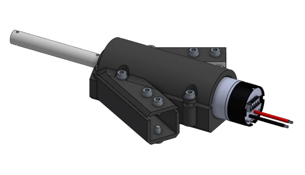
Since my last blog post discussing my summer robotics projects, I’ve been working on my design for a three-omni-wheeled holonomic “TriangleBot” robot. The obvious next step for me was to decide on what I would use for drive motors, I thought about using Johnson Electric PLG Gearmotors because I have 3 on hand and they provide the neccesary gearing without any additional hassle, after throwing together some initial designs using these motors, I came across a few different issues that led me to rethink my choice of motors.
-
I have 3, but one of them is a different variant with a higher gearing ratio :(
-
The specifications say to specifically avoid side loading the shaft, which is difficult to avoid with the space saving cantelievered wheels in my design
-
With the 4” omni wheels I’m planning on using, the robot would move about 4mph, which is pretty fast, but I’d like my robot to be super zoomy
-
The shaft for the motor is nonstandard, difficult to make, and expensive to buy (the motor has an internal spline, I would likely have to machine a custom square shaft to fit inside)
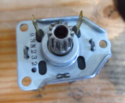
As I was going through my box of motors looking for alternatives, I found a couple of peculiar motors: Denso throttle motors. These motors were in the FRC kit of parts a few years back and many FRC teams - including mine - have them in excess nowadays. Here are some details:
-
5,300 RPM free speed (roughly the same as a CIM motor) but about 1/15th the torque.
-
Power terminals on the same side as output shaft
-
12-tooth 0.75mm pitch gear output
-
0.4A free, 17A stall
The reason many teams don’t use throttle motors often is that they’re quite difficult to use, because of the inconvenient power connectors and gear rather than a spline or keyed shaft like many other FRC motors. For me, the geared output shaft was actually quite useful because the only manufacturing that I have access to at home is a 3D printer, and for 3D printing, having a non-standard gear pitch is no problem at all.
Initial Design:
To start out, I needed a rough estimate of what gearing ratio I would need given the motor’s high RPM. I decided that around a 10:1 gear ratio would be adequate. I started working on some CAD for a gearbox and made some design decisions along the way:
-
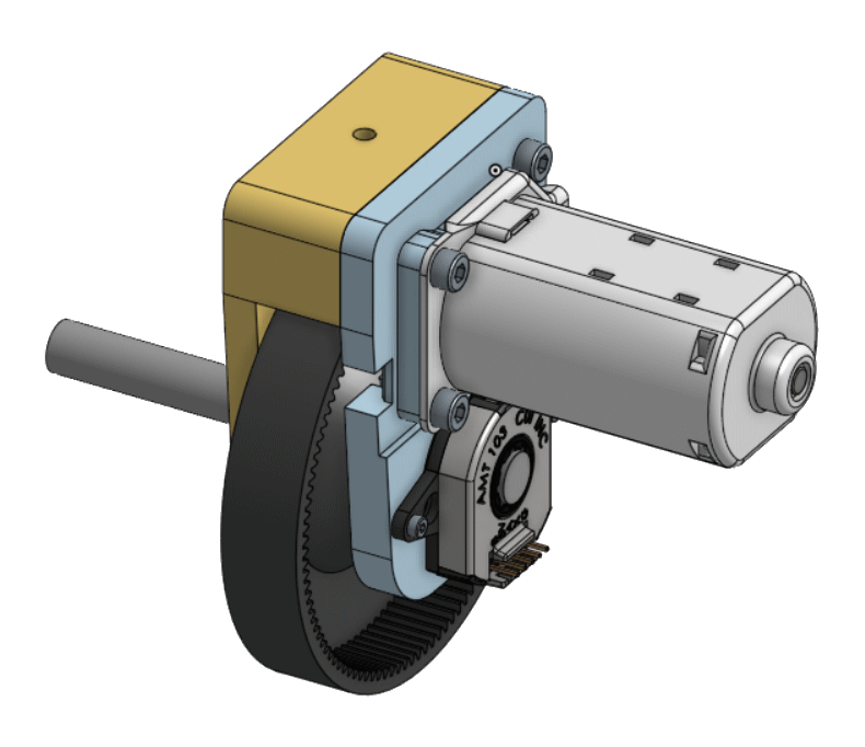
Use an internal ring gear with a 9:1 ratio rather than an external spur gear would save space and allow for a more sturdy 3D print
-
Mount bearings on both sides of the shaft because cantilevered wheels put a side load on the output shaft
-
Attach an encoder to the output shaft for the wheel. (This was actually quite easy, since the motor was offset from the output shaft I would have room to mount an encoder on the back of the gearbox)
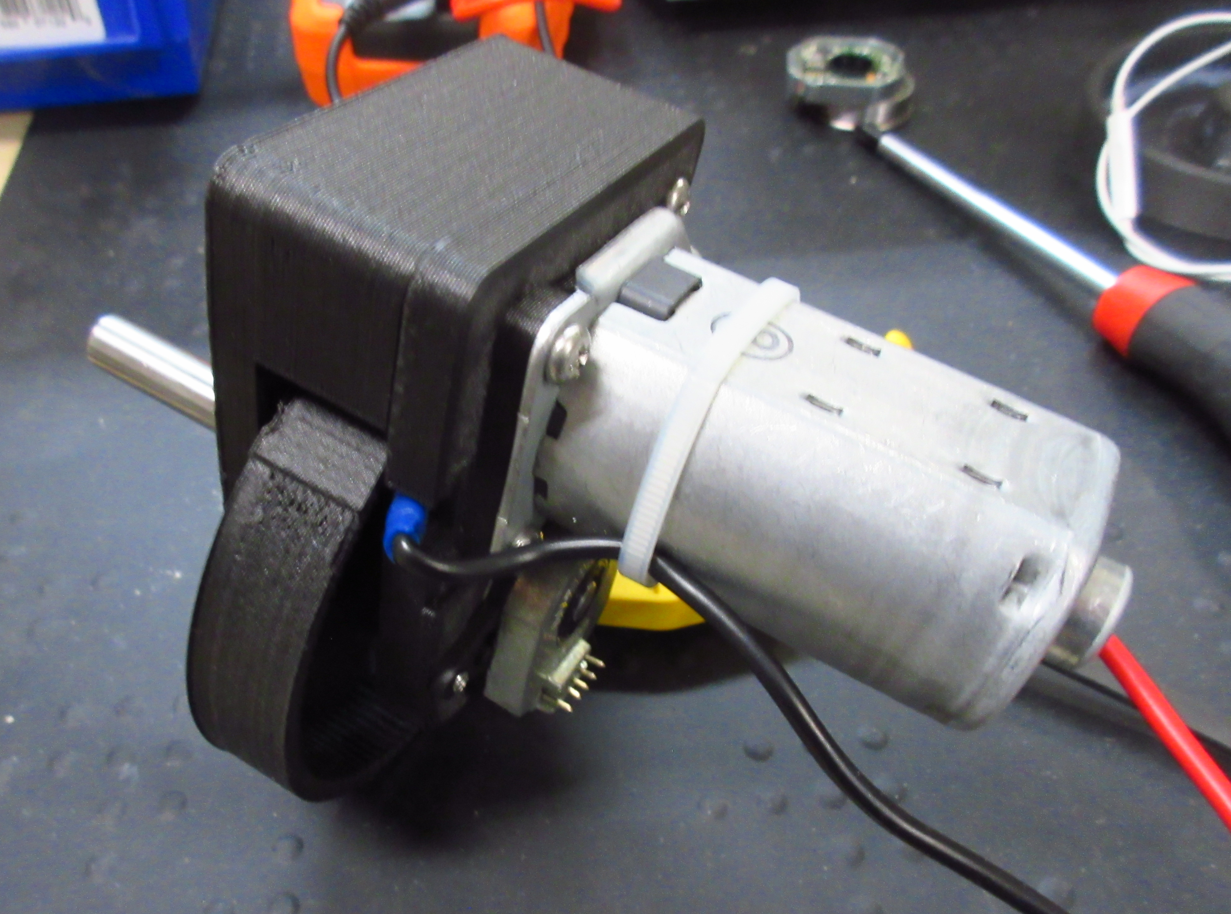
I chose to put an AMT103 high precision encoder on the back of the gearbox coupled directly to the output shaft because I had a few of them on hand. After some work implementing these specifications, my gearbox design ended up being three pieces: a central ring gear, front mounting plate, and a back plate to hold the motor and encoder. To deal with the issue of getting power to the motor I simply folded the motor’s power leads to the side. Initially I planned on using half inch hex shaft for the output of the gearbox but since I don’t have any of that on hand I decided instead to pressure fit the gear on a 3/8in output shaft, made from a bolt with the head cut off.
Testing!
After printing and assembly of the gearbox I was surprised that the motor actually fit quite well and meshed with my ring gear without significant resistance. I spun the motor up and was happy to see that my gearbox didn’t seem to have a huge amount of resistance, only drawing a couple more milliamps than the motor spinning free. After these initial rough observations, I decided to take it a step further and actually profile my motor and gearbox. To do this I wrote a program that would sweep the motors input voltage (via a motor controller) through all of its range and measure the output speed using the encoder. I fed this recorded data into a CSV file and plotted it using Google Sheets. The speed data was quite noisy, probably due to the fact that I measured the speed using the pulse width of one of the encoder’s signals, so I post-processed it using a moving average filter. My data was still quite noisy but I could definitely see a linear relationship between the motors input voltage and output - as it should be for a permanent magnet DC motor. In the future, I plan on using a linear regression of this data to provide feedforward for all of my robot’s wheels.
Final Thoughts:
Although it was better than I expected, not everything about this gearbox was all well and good. First of all I found it quite difficult to pressure fit the gear onto the 3/8 in shaft perfectly straight, and the oscillation of the skewed gear on the shaft was very noisy, not a huge issue, but certainly something that I aim to improve in the future. In trying to fix the bad pressure fit on my first gear I actually ended up breaking the hub in the center of the gear off which led to a redesign of the gear to strengthen the center bore and hub. I had also planned on using 3D printed plastic spacers to provide clearance between the gear and the sides of the gearbox but I discovered that when running these plastic spacers at high speeds it ended up sort of stir-welding them to the sides of the gearbox - not good. Fix this I just used metal 3/8 in washers which solved the problem for now.
Now that I have a decent gearbox designed, I’m moving on to designing the frame for my robot and working out how the electronics will be constructed. Keep posted for more updates!
